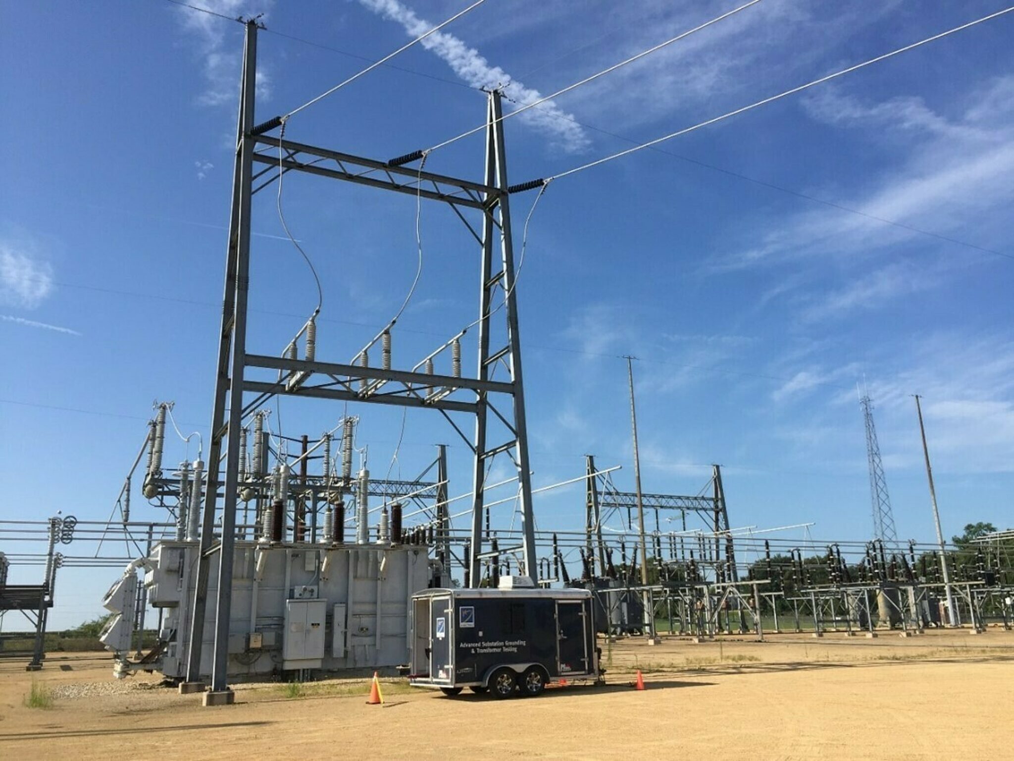
Ground Grid Testing Overview
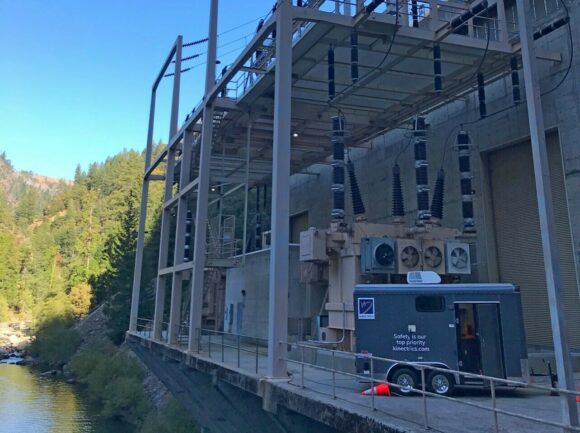
Ground grid testing provides confidence in the proper design and performance of the grounding system in terms of meeting safety requirements of personnel working inside the substation and outside the fenced area of high voltage yards as prescribed in IEEE 80.
It also verifies major design parameters such as ground potential rise, ground impedance, step and touch potentials, and current splits into external ground connections. These tests comply with the IEEE 81 guidelines that outline the proper procedures for these measurements.
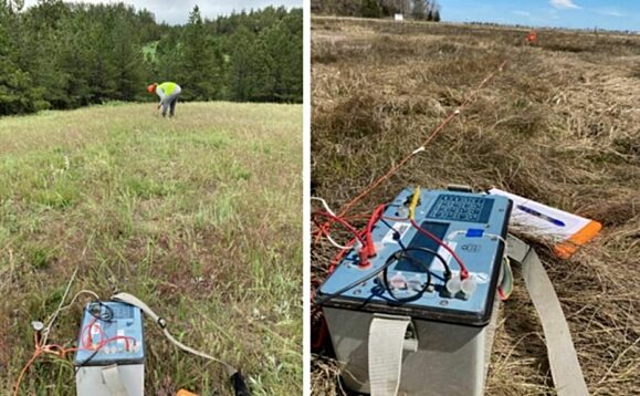
Our core testing methodology is based on current injection testing (CIT) which injects a low amplitude and off-frequency test current to the grounding system to duplicate down-scaled real fault scenarios. The CIT is performed by either injecting from auxiliary test electrodes thousands of feet outside the station (overland injection) or by using a de-energized circuit that is isolated and grounded for the tests. We also perform integrity testing to evaluate the integrity of all above-grade bonds as well as buried ground conductors. These tests include injecting a 1 – 10 A DC test current between accessible bonds, measuring the micro-ohm resistance, and comparing that with the resistance estimated by the modeled mesh of resistances created based on the conductor layout.
Why Our Ground Grid Testing?
-
Safety Assurance
Ground grid testing ensures the safety of personnel working inside the substation and the general public outside its fenced area.
-
Extensive Experience
With extensive experience conducting risk assessments, our team is able to reduce vulnerability to lightning damage.
-
Cost Saving
Significant savings in deferring substation upgrades can be realized if it is found that the ground potential rise is lower than expected from the theoretical design calculations.
-
Reliable Operations
We add confidence to the design calculations by reviewing the electrical safety of the station, and investigating, developing, and applying mitigation solutions.
Our Ground Grid Testing Technical Abilities
Grounding Main Services
Our grounding services can be divided into two main categories, Category A and Category B.
Category A tests are focused on the original design of the grounding system and evaluate the performance of the existing grounding system during simulated fault conditions. They include Soil Resistivity Tests, Current Injection Tests, and Step and Touch Voltage Measurements.
Category B tests focus on evaluating the integrity of ground conductors and include Integrity Tests and Stone Resistivity Tests.
We recommend performing Category A tests post-commissioning of a new substation or when establishing a baseline performance if no commissioning records are available. Category B tests should be included in the 5 to 10-year maintenance program or after any major construction or upgrade projects, equipment failure, lightning event, or signs of broken or corroded ground conductors.
Soil Resistivity Tests
Soil resistivity data enables modeling of the isolated station ground resistance from geometry, safe body withstand potentials when standing on native soil and the Carson (earth return) impedance. Soil modeling is an essential part of calculating the ground impedance of the grounding system.
Current Injection Testing (CIT)
Measurement of the interconnected ground impedance, when scaled for system fault levels at appropriate locations, gives an estimate of the maximum ground potential rise. If the ground potential rise exceeds 5 kV, additional attention must be paid to step and touch potential coordination. Clients frequently find that the ground potential rise is, in fact, much lower than they expected from previous theoretical design calculations where the benefits of interconnections were neglected. This reduction can provide significant savings in deferring substation upgrades.
Current splits are measured on external interconnections to define their individual contribution to reducing the ground potential rise. This validates the modeling assumptions used in grounding design. The remaining current split in the ground electrode allows for finding the isolated station ground resistance, for comparison to design calculations.
Step and Touch Voltage Measurement
The magnitude of step and touch voltages during fault conditions must be measured to ensure the safety of personnel working inside the substation and of the general public who may be outside its fenced area. During fault conditions, potentials such as touch on locally grounded equipment inside the substation, touch on substation fence, step voltage while walking inside the substation, and step voltage outside the substation on native soil must comply with the allowable limits specified in IEEE Std 80.
Integrity of Grounding Grid and Bonding Conductors
Integrity tests compare the measured resistance between the identified objects and the modeled resistance based on conductor size, length, and amount of meshing in order to identify missing or broken underground conductors and connectors. Every ground pigtail is tested to confirm the integrity of the connection to the buried grounding system. Special attention is paid, during the tests, to identify and report above-grade connectors that are not in compliance with IEEE 837.
Stone Resistivity Test
The surface stone resistivity test checks the insulating quality of the material used in covering yards, relative to the 3,000 Ωm typically used during design calculations. This impacts the safe body withstand between the foot and hand, and foot to foot. Stone is vulnerable to contamination by weeds, wind-blown dust, and invasion by subsoil.
Grounding Test Report
The grounding test report is a technical engineering report that includes the test results, visual observations of grounding system condition, projections of results to worst fault levels and locations, models that corroborate the test results, comparisons with safe body withstands, and conductor capability. The report is concluded with recommendations for mitigation and recommended priorities.
Our Proven Experience
Quality Assurance & Technical Standards
- IEEE 367-2012
- IEEE Recommended Practice for Determining the Electric Power Station Ground Potential Rise and Induced Voltage from a Power Fault
- IEEE 80 (2013)
- IEEE Guide for Safety in AC Substation Grounding
- IEEE 81 (2012)
- IEEE Guide for Measuring Earth Resistivity, Ground Impedance, and Earth Surface Potentials of a Grounding System
Key Clients
The Kinectrics team performed the testing in a timely manner. They interacted very well with the Exelon field personnel for this work. The engineering work behind the testing work was excellent and provides a lot of value to Exelon engineering. The project deliverables were of very high quality. Exelon is planning on employing Kinectrics for Ground Grid Testing next year.


